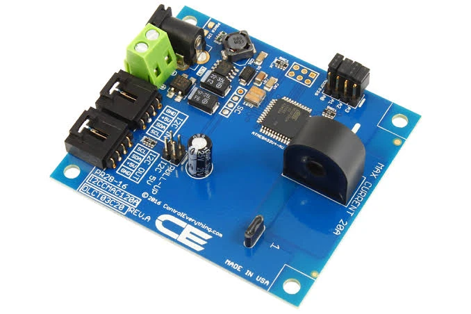

Knowing how much current and power a circuit is using has moved from a nice-to-have to a requirement. Battery-powered products need it to estimate remaining run time. Servers and network equipment need it for power budgeting and fault detection. Chargers and solar controllers need it to do their job at all. And during development, a current reading you can log from firmware is one of the fastest ways to find out where the energy is going.
The simplest way to add that capability is a digital power monitor: a chip that measures the voltage across a shunt resistor and the bus voltage, does the multiplication, and reports the results over I2C. This article reviews the monitors that engineers choose most often, beginning with the one that offers the best balance for most designs, and explains how to pick between them.
How a digital power monitor works
A power monitor contains a precision amplifier, an analog-to-digital converter and a small amount of digital logic. A low-value shunt resistor is placed in series with the load. The monitor measures the voltage across the shunt, which is proportional to current, and the voltage on the bus. With a calibration value that represents the shunt resistance, it calculates current and power internally. Some devices go further and accumulate energy and charge over time.
Compared with an analog current-sense amplifier feeding a microcontroller’s ADC, a digital monitor offers better accuracy, removes the need for a precision reference, and puts the sensitive analog measurement right at the shunt, with only digital signals running back to the processor.
What to compare
- Bus voltage range. The maximum voltage the monitor can sense. This is separate from the chip’s own supply voltage.
- Resolution and shunt voltage range. Together these set how small a current you can resolve for a given shunt.
- Accuracy. Offset error controls accuracy at low current. Gain error controls accuracy at high current.
- Channels. One monitor per rail, or one chip for several rails.
- Alerts. A programmable output that signals overcurrent or other faults without software polling.
- Energy accumulation. Built-in totals of energy or charge, useful for fuel gauging and billing.
- Integrated or external shunt. An integrated shunt saves design effort and board space but fixes the current range.
- Interface and addressing. How many devices can share one bus.
- Supply current. Important in battery-powered designs.
1. Texas Instruments INA226
The INA226 is the reference point for single-rail monitoring below 36 V. It combines a 16-bit converter with very low offset and gain error, in a small package and at a moderate price.
- Bus voltage range of 0 to 36 V, independent of the supply
- Shunt voltage range of plus or minus 81.92 mV with a 2.5 microvolt step
- Bus voltage step of 1.25 mV
- Maximum gain error of 0.1 percent and maximum offset of 10 microvolts
- Reports current, bus voltage and power
- Programmable conversion times and averaging of up to 1,024 samples
- Alert pin with selectable function: over or under limits on shunt voltage, bus voltage or power, or conversion ready
- Sixteen selectable I2C addresses
- 2.7 to 5.5 V supply, about a third of a milliamp in operation
- 10-pin VSSOP package
Strengths. The low offset gives accurate readings across a wide span of current on one shunt. The alert pin allows hardware-speed fault response. Sixteen addresses make it easy to monitor many rails. Libraries are available for every common platform.
Limits. It does not accumulate energy internally, so the host must integrate power over time. It tops out at 36 V. It needs an external shunt.
Best for. Battery packs, chargers, solar controllers, bench instruments, 12 V and 24 V industrial rails, and power profiling during development.
The standard order code on a full reel is the TI INA226AIDGSR. It is listed by Verified Electronics, a distributor of electronic components that carries Texas Instruments products and uses third-party testing.
2. Texas Instruments INA219
The INA219 is the older, simpler relative. It has a 12-bit converter, a bus range of 0 to 26 V, a programmable gain amplifier with shunt ranges from 40 mV to 320 mV, and gain error of 1 percent or 0.5 percent depending on grade. It has no alert pin.
Strengths. Low cost, an easy-to-solder SOIC-8 option, and the largest collection of tutorials and example code of any current monitor.
Limits. Coarser resolution, larger offset and a lower voltage ceiling than the INA226.
Best for. Basic monitoring of 5 V and 12 V rails, teaching and quick prototypes.
3. Texas Instruments INA228 and INA238
These are the high-voltage, high-precision members of the line. Both sense bus voltages up to 85 V, which covers 48 V systems with margin. The INA238 has a 16-bit converter. The INA228 has a 20-bit converter and adds on-chip accumulation of energy and charge, along with a die temperature sensor that can be used to compensate for shunt drift. Both offer two selectable shunt ranges and an alert output.
Strengths. The voltage range opens up 48 V telecom, e-bike, power-tool and industrial applications. The INA228’s resolution and accumulators make it suitable for precise energy measurement and battery fuel gauging.
Limits. Higher cost than the INA226, and more registers to configure.
Best for. 48 V buses, battery energy tracking and applications where the last fraction of a percent matters.
4. Texas Instruments INA260
The INA260 takes the measurement core of the INA226 and adds a precision 2 milliohm shunt inside the package. It measures up to 15 A continuously on buses up to 36 V, with 1.25 mA current steps, and it is calibrated as a complete system at the factory.
Strengths. No shunt to choose, no Kelvin routing to get right and no calibration register to compute. The accuracy figure in the datasheet includes the shunt. It saves board area and design time.
Limits. The current range is fixed. For low-current measurement its 1.25 mA step is coarse, and for more than 15 A it cannot be used. The load current flows through the package, so the board must carry that current to the chip.
Best for. Designs between about 1 A and 15 A where simplicity and guaranteed system accuracy matter more than flexibility.
5. Texas Instruments INA3221
The INA3221 monitors three independent channels with one chip. Each channel measures shunt voltage and bus voltage on rails up to 26 V. It provides warning and critical alert outputs with programmable limits, and it can sum the shunt voltages across channels to watch total current.
Strengths. One device and one I2C address for three rails, which reduces cost and board space in multi-rail systems. The separate critical and warning outputs suit supervisory circuits.
Limits. Resolution is lower than the INA226, with a 40 microvolt shunt step. It does not compute current and power internally, so the host does the arithmetic. It offers four addresses.
Best for. Monitoring 3.3 V, 5 V and 12 V rails together in embedded computers, FPGA boards and networking equipment.
6. Microchip PAC1934 family
The PAC193x family offers one to four channels in a single package, with a bus range up to 32 V and 16-bit measurement. Its distinguishing feature is on-chip power accumulation: it samples continuously and keeps running totals for each channel, so the host can read energy use over long intervals without waking frequently.
Strengths. Energy accumulation across four rails with very little host activity, which suits system-level power profiling in battery-powered computers and tablets. The fixed full-scale shunt range of 100 mV is slightly wider than the INA226.
Limits. The register interface is more involved, and community libraries are fewer.
Best for. Multi-rail energy measurement in portable and embedded computing.
7. Analog Devices LTC2945
The LTC2945 is a wide-range monitor that senses buses from 0 to 80 V and can itself be powered from a high-voltage rail, with a built-in shunt regulator for even higher supplies. It has a 12-bit converter, measures current, voltage and one auxiliary input, calculates power, and stores minimum and maximum values with programmable alert thresholds.
Strengths. It operates directly on high-voltage buses without a separate low-voltage supply, and records peak values without host intervention.
Limits. Twelve-bit resolution, and a higher price than the TI parts.
Best for. Telecom, industrial and automotive rails where the monitor must live on the high-voltage bus.
Comparison table
| Part | Channels | Maximum bus voltage | Resolution | Shunt | Alert | Energy accumulation |
|---|---|---|---|---|---|---|
| INA226 | 1 | 36 V | 16-bit | External | Yes | No |
| INA219 | 1 | 26 V | 12-bit | External | No | No |
| INA238 | 1 | 85 V | 16-bit | External | Yes | No |
| INA228 | 1 | 85 V | 20-bit | External | Yes | Yes |
| INA260 | 1 | 36 V | 16-bit | Integrated, 2 milliohms | Yes | No |
| INA3221 | 3 | 26 V | 13-bit | External | Yes | No |
| PAC1934 | 4 | 32 V | 16-bit | External | Yes | Yes |
| LTC2945 | 1 | 80 V | 12-bit | External | Yes | No |
These are headline values. Check the current datasheet for each part before designing it in.
Choosing by application
Single battery pack up to about 30 V. INA226. Use the alert pin for overcurrent, and integrate power in firmware if you need energy.
Battery fuel gauging with coulomb counting. INA228, for its charge and energy accumulators and higher resolution.
48 V systems. INA238 or INA228, or the LTC2945 if the monitor must be powered from the bus.
Several low-voltage rails on one board. INA3221 for three rails, or a PAC193x device for up to four with energy totals.
Fastest path to a working measurement. INA260, if the current falls within its range.
Lowest cost for rough monitoring. INA219.
Development-time power profiling. INA226 with a shunt sized for your current span, logging at a few hundred readings per second.
Design advice that applies to all of them
- Size the shunt to the input range. Aim for 50 to 75 percent of the full-scale shunt voltage at maximum current.
- Match the shunt to the chip. A 0.1 percent monitor deserves a shunt with tight tolerance and a low temperature coefficient.
- Use Kelvin connections. Route separate sense traces from the inner edges of the shunt pads, as a close pair, with no load current sharing the copper.
- Keep input filter resistors small. Bias current through large filter resistors adds error.
- Use averaging. Built-in averaging reduces noise from switching loads without adding error.
- Plan the addresses. Assign address pins early when several monitors share a bus.
- Wire up the alert pin. Even if the first firmware release does not use it, having it connected to an interrupt-capable pin keeps the option open.
- Mind the bus speed. Long wires and many devices add capacitance. Choose pull-up values to suit.
Digital monitor or analog amplifier?
A digital monitor is the right tool when you want accurate average current, voltage and power with minimal design effort. An analog current-sense amplifier is the right tool when you need bandwidth: closing a current control loop in a motor drive or switching converter, or tripping a protection circuit within microseconds. The update rate of a digital monitor is measured in hundreds or thousands of readings per second, which is too slow for those jobs. Many designs use both, with an amplifier for control and a monitor for telemetry.
Frequently asked questions
Which monitor is the most accurate? Among those listed, the INA228 has the highest resolution and the tightest specifications. The INA226 is close behind and sufficient for most designs.
Can these monitors measure current in both directions? Most can, including the INA226, INA228 and INA260. They report signed values.
Do I need a separate monitor per rail? Not with multi-channel devices such as the INA3221 and PAC1934.
Can they sense on the low side? Yes. Parts that accept 0 V common mode work on either side of the load. High-side sensing is usually preferred.
How do I measure energy with a monitor that lacks an accumulator? Read power at regular intervals and sum the readings multiplied by the interval. Averaging in the chip helps capture pulsed loads.
Summary
For a single rail up to 36 V, the INA226 is the best all-round choice: 16-bit resolution, 0.1 percent gain error, very low offset and a flexible alert pin. Choose the INA219 when cost and simplicity come first, the INA228 or INA238 for 48 V systems and energy tracking, the INA260 when you want the shunt built in, and the INA3221 or PAC1934 when several rails need watching. Whatever the choice, the shunt resistor and its layout determine how much of the chip’s accuracy reaches your readings.